


Huawei’s NE40 series—particularly the M2K and M2K-B models—is becoming the new “favorite” among ISPs in Brazil, enabling a variety of deployment scenarios with excellent cost-effectiveness, both at the network core layer (BGP, aggregation routers, and the like) and the access layer (IPoE BNGs, PPPoE, etc.).
Recently at Made4it, we had a case where a customer with an NE40E-M2K-B needed chassis-level virtualization so that a partner could also take advantage of the chassis’s resources, but with a certain level of segregation.
With our knowledge and expertise with the vendor, we suggested and designed a Virtual System in the box for this purpose, and, following the vendor’s recommendation, we informed the customer that the communication between the “virtual-systems” should be through dedicated network ports, where we would have a “physical loop” to deliver data to the partner’s “virtual-system”. Here in the company, we have come to affectionately call this feature the “coffin strap” (laughs).
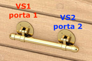
With this, the first way to link two VS is simply to connect a cable between two ports on the same router, allocating each port to a single VS.
Se quer saber mais sobre virtualização de roteadores Huawei, consulte o post Roteadores Virtuais (VS / Virtual-System) no Huawei NE
In this same scenario, a while back we carried out an implementation where his requirement was simple, basically:
“My carrier is connecting to me through two different devices on my network: a BGP router and an MPLS switch located 40 km from here. The carrier wants to use MPLS with me. I need to route MPLS on my NE40, where the carrier will provide me with circuits on some VPWSs.”
In this case the deployment went smoothly, using the “Virtual Ethernet ” feature where the “layer2” side and the “layer3” side have distinct interfaces to work the VPWS and do the IP connectivity respectively.
If you don’t know about MPLS on NE routers, or if the concept of “layer2 side” or “layer3 side” didn’t make sense, see the post L3 Interfaces in L2 MPLS Tunnels on Huawei NE Router (How to configure MPLS with IP on Huawei)
The other way to link…
In our constant, daily exchanges of experience between the N2 and N3 teams, one of our consultants had an insight in a moment of reverie (usually in the shower, in the bathroom, opening the fridge, walking, etc):
“We know that a virtual Ethernet has a Layer 2 side and a Layer 3 side.
And we know that we can place one of these sides in a virtual system other than the admin system, since virtual Ethernet interfaces can only be created in the admin virtual system. Now imagine: if we created two different VE groups and used an MPLS circuit-cross-connection (CCC) to link these two Layer 2 sides, would it be possible for the virtual systems to communicate at Layer 3 without needing the loopback link?”
Just to name a few, CCC is the most basic, non-signaling way to connect two services via a VPWS.
Then we set out to test the interconnection of two local VS via an MPLS CCC.
Interconnecting two VS via VPN VPWS CCC
Scenario:
For our tests we will use two VE-GROUPs, interconnect the L2 of the VE-GROUPs via CCC VPWS, and keep one side L3 in Admin-VS while the other side L3 we will put in VS1.

Settings:
First, we will create the interfaces that will be part of L2:
# Admin-VS

! Side L2 Admin-VS

Virtual-Ethernet0/2/100 interface
  ve-group 100 l2-terminate

Virtual-Ethernet0/2/100,100 interface
  vlan-type dot1q 100

! Side L2 VS1

Virtual-Ethernet0/2/200 interface
  ve-group 200 l2-terminate

Virtual-Ethernet0/2/200.100 interface
  vlan-type dot1q 100
After that we will interconnect VLAN 100 via VPN VPWS CCC:
! MPLS CCC VPWS interconnection
ccc test interface Virtual-Ethernet0/2/100.100 tagged out-interface Virtual-Ethernet0/2/200.100 tagged
With layer2 configured, we can move on to activating the L3 services:
# Admin-VS

! Side L3 Admin-VS

Virtual-Ethernet0/2/101 interface
  mac-address c4b8-b434-ab45
  ve-group 100 l3-access

interface Virtual-Ethernet0/2/101.100
  vlan-type dot1q 100
  ip address 10.1.1.1 255.255.255.252


! Side L3 VS1

interface Virtual-Ethernet0/2/201
  ve-group 200 l3-access

interface Virtual-Ethernet0/2/201.100
  vlan-type dot1q 100
Finally, we will insert only the L3 subinterface for VS1.
# Admin-VS
admin
 virtual-system vs1 pvmb slot 3
 port-mode port
 assign interface Virtual-Ethernet0/2/201.100


# VS1

! VS1 L3 Side
interface Virtual-Ethernet0/2/201.100
 vlan-type dot1q 100
 ip address 10.1.1.2 255.255.255.252
Scenario Considerations
Some considerations of the scenario:
- It was only possible to add a vlan subinterface in the virtual-system, it did not allow the entire virtual-ethernet
- It was necessary to change the mac-address of the Virtual-Ethernet on one side, because the VS inherits the mac from the chassis
Validations
CCC between virtual-ethernets up:
<HUAWEI>display vll ccc
total ccc vc : 1
local ccc vc : 1, 1 up
remote ccc vc : 0, 0 up

name: teste, type: local, state: up,
intf1: Virtual-Ethernet0/2/100.100 (up), access-port: false

intf2: Virtual-Ethernet0/2/200.100 (up), access-port: false

VC last up time: 2020/02/17 14:40:58
VC total up time: 0 days, 0 hours, 16 minutes, 37 seconds
Ping between the two VS:
Admin-VS:
<HUAWEI>ping 10.1.1.2
 PING 10.1.1.2: 56 data bytes, press CTRL_C to break
 Reply from 10.1.1.2: bytes=56 Sequence=1 ttl=255 time=1 ms
 Reply from 10.1.1.2: bytes=56 Sequence=2 ttl=255 time=1 ms
 Reply from 10.1.1.2: bytes=56 Sequence=3 ttl=255 time=1 msd
 Reply from 10.1.1.2: bytes=56 Sequence=4 ttl=255 time=1 ms
 Reply from 10.1.1.2: bytes=56 Sequence=5 ttl=255 time=1 ms

 --- 10.1.1.2 ping statistics ---
 5 packet(s) transmitted
 5 packet(s) received
 0.00% packet loss
 round-trip min/avg/max = 1/1/1 ms


VS1:
<HUAWEI-vs1>ping 10.1.1.1
  PING 10.1.1.1: 56 data bytes, press CTRL_C to break
  Reply from 10.1.1.1: bytes=56 Sequence=1 ttl=255 time=1 ms
  Reply from 10.1.1.1: bytes=56 Sequence=2 ttl=255 time=1 ms
  Reply from 10.1.1.1: bytes=56 Sequence=3 ttl=255 time=1 ms
  Reply from 10.1.1.1: bytes=56 Sequence=4 ttl=255 time=1 ms
  Reply from 10.1.1.1: bytes=56 Sequence=5 ttl=255 time=1 ms

  --- 10.1.1.1 ping statistics ---
  5 packet(s) transmitted
  5 packet(s) received
  0.00% packet loss
  round-trip min/avg/max = 1/1/1 ms<HUAWEI>ping 10.1.1.2
  PING 10.1.1.2: 56 data bytes, press CTRL_C to break
  Reply from 10.1.1.2: bytes=56 Sequence=1 ttl=255 time=1 ms
  Reply from 10.1.1.2: bytes=56 Sequence=2 ttl=255 time=1 ms
  Reply from 10.1.1.2: bytes=56 Sequence=3 ttl=255 time=1 msd
  Reply from 10.1.1.2: bytes=56 Sequence=4 ttl=255 time=1 ms
  Reply from 10.1.1.2: bytes=56 Sequence=5 ttl=255 time=1 ms

  --- 10.1.1.2 ping statistics ---
  5 packet(s) transmitted
  5 packet(s) received
  0.00% packet loss
  round-trip min/avg/max = 1/1/1 ms
Test using a BGP session and OSPFv2 and OSPFv3 adjacencies:
<HUAWEI>display bgp peer

 BGP local router ID: 192.168.88.100
 Local AS number: 11111
 Total number of peers: 1 Peers in established state: 1

 Peer V AS MsgRcvd MsgSent OutQ Up/Down State PrefRcv
 10.1.1.2 4 22222 25 25 0 00:19:38 Established 0

<HUAWEI>displ ospf peer brief

(M) Indicates MADJ neighbor


 OSPF Process 1 with Router ID 10.0.0.1
 Peer Statistics Information
Total number of peers: 1
 Peers in full state: 1
-----------------------------------------------------------------------------
 Area Id Interface Neighbor id State
 0.0.0.0 VE0/2/101.100 10.0.0.2 Full

<HUAWEI> displ ospfv3 peer
 OSPFv3 Process (1)
 OSPFv3 Area (0.0.0.0)
 Neighbor ID Pri State Dead Time Interface Instance ID
 10.0.0.1 1 Full/DR 00:00:38 VE0/2/201.100 0
Finally that’s it folks, we don’t know the performance or impact on the box, but the basic services worked normally.
If you test it with traffic, let us know! Share your results with us.
If you need assistance, please contact us!
Hugs,
Rafael Ganascim, Gabriel Henrique and Kevin Walters
IT Consulting Team – Made4it