




“Multi Protocol Label Switching” is a mechanism in high-performance telecommunications networks that directs data from a network node to the next node based on shortest path labels ( Labels ) instead of network addresses ( Routes ), avoiding queries complexes in a routing table.
One of the benefits of MPLS, in addition to its interoperability with various types of technologies such as E1, xDSL, ATM, and Ethernet, is the ability to create “VPNs” at both Layer 2 and Layer 3.
Huawei’s “NE” series allows us to use MPLS and VPN features, where the MPLS activation process itself is the same as on any other router designed for this purpose. The prerequisite is:
- Properly configured IGP
- Loopback interface properly configured with IP /32
- Redistribution of routes in IGP
For MPLS activation, on the NE40, assuming the loopback IP is 10.1.1.1:
[huawei] mpls lsr-id 10.1.1.1
[huawei] mpls
[huawei] mpls l2vpn
After that, we need to activate the protocols on the interfaces that will be part of MPLS
interface giga0/3/22.182
 mpls
 mpls te
 mpls rsvp-te
 mpls ldp
Virtual-Ethernet
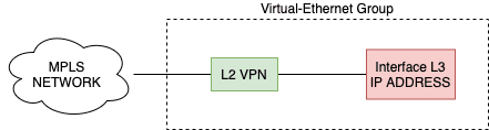
Virtual Ethernet is used when we have the need to do services of “Layer 2” e “Layer 3” on the same device.
We know that, in a VLL in Martini mode, for example (MPLS + L2VC), it is not permitted to apply Layer 2 configurations (“l2 binding vsi” or “mpls l2vc”) and Layer 3 (“ip address x.x.x.x”) on the same interface; they must be properly “separated.”
Until now, in applications of this level, it has been common to implement the “Layer 2/MPLS/VLLs” side on switches or dedicated equipment designed for this purpose, however, using virtual Ethernet on Huawei makes it perfectly possible to implement an MPLS approach, use L2VC or VPLS tunnels, and still handle “Layer 3” using only the device (router) without the need for other equipment for this purpose.
Using the concept of “Virtual-Ethernet” in Huawei, we created two virtual interfaces that are properly “linked” where each of them belongs to a “side” being “layer 2” and “layer3”.
Possible applications
- Redundancy based on MPLS and iBGP/BGP sessions where OSPF/MPLS and BGP work on the same box.
- MPLS based redundancy for BNG scenarios ( IPoE / PPPoE ) where OSPF/MPLS and PPPoE-Service work on the same box.
- Scenarios for Layer2 VPNs accessing a public network.
- Scenarios for Layer 2 VANs accessing a Layer 3 VPN.
Limitations
- “VE Groups” are only supported in “Virtual System” admin.
- There is a limitation of 3 “VE Groups” per box (in case of NE40E-M2K)
Configuration example 1
Consider a scenario where we want to “terminate” an L2VC tunnel and, on the same device, close an eBGP session with a remote host (within that VLL) using virtual Ethernet. We’ll receive it on an L2VC with ID “301” and also use a VLAN with ID “301” to establish the eBGP session with our remote provider.
Prerequisites:
- Communication interfaces with “UP” and “Running” network equipment
- Communication interfaces with properly addressed network equipment
- IGP duly aligned on all network equipment.
- Loopbacks properly defined on all network equipment.
- Duly closed LDP sessions on all network devices.
- L2VPN properly aligned on the remote host.
Settings:
Let’s create the virtual interface, and define it with the L2 function. The VE-GROUP is the 1.
virtual-ethernet interface 0/1/1
 ve-group 1 l2-terminate
After that, let’s create the L3 pair of the virtual interface.
virtual-ethernet interface 0/2/1
 ve-group 1 l3-access
With these configurations, we have the “VE0/1/1” and “VE0/2/1” interfaces properly associated, where the “0/2/1” interface is responsible for the “layer3” side while the “0/1/1” ” is responsible for the “layer2” side. What properly associates the interfaces is the “ve-group”, where interfaces of the same group are associated with each other.
Now, we have to close the “L2VC” with our remote operator. For this, we are going to create a subinterface with ID “301” on the “layer2” side of our “virtual-ethernets”. And after that create the L2VC VPN with the remote PE.
virtual-ethernet interface 0/1/1.301
 vlan-type dot1q 301
 description L2-Terminate 301 - L2VC Binding
 mpls l2vc 10.1.1.4 301 raw
With that, we have the “layer2” side ready. We now have to configure the “layer3” side with settings related to IP connectivity.
Let’s assume that our ISP has assigned us the IP address 192.168.10.2/30 to establish an “eBGP” connection. Therefore, we need to create the interface “VE0/2/1.301” and configure it with this information.
virtual-ethernet interface 0/2/1.301
 vlan-type dot1q 301
 ip address 192.168.10.2 30
 description L3 VPN termination for VPWS NE
As we can see, the “VE0/1/1” and “VE0/2/1” interfaces are properly associated, where the “subinterfaces”—both of which are part of the same “ve-group”—are properly associated for whatever purpose, each performing its function as specified, whether “l2-terminate” or “l3-access.”
If you have any questions, please contact us! We’re here to help you.
Cordial hugs,
Gabriel Henrique
IT Consulting Team – Made4it