
How to configure MC-LAG on Huawei: E-Trunk, Eth-Trunk, LACP and BFD step by step.
Learn MC-LAG in Huawei, today we show you why E-Trunk (multi-chassis), when to use Eth-Trunk (aggregation), how to adjust LACP for active/backup ports and how BFD shortens MTTR. We include recommendations for hashing in MPLS scenarios and a test script to validate failure behavior.
Link-aggregation (LAG), called Trunk at Huawei(Eth-Trunk when it’s Ethernet), is a technology that combines multiple physical interfaces into a single logical interface. With link-aggregation we win:
- increase in bandwidth (sum of links),
- redundancy,
- and rapid convergence on interface/link failures.
Traditional LAG is always between two devices, point to point:

Types of LAG for Huawei
Quite simply, at Huawei we have three main ways of using Eth-Trunk:
- Manual (manual load-balancing)
- Static LACP
- Manual 1:1 master/backup
In the context of MC-LAG, what matters to us is basically:
- Eth-Trunk manual
- Eth-Trunk in LACP static
Let’s make it simple:
- You create Eth-Trunk, add the interfaces and you’re done.
- All trunk interfaces are active and forwarding traffic.
- There is no negotiation with the other side, so the “criterion” is just the configuration to beat (same number of ports, speed, duplex, etc.).
Static LACP
- You also create Eth-Trunk and add the interfaces, but their status (active or backup) is decided by LACP.
- LACP exchanges messages (LACPDUs) between the two sides, decides which links can be part of the LAG and which will be active or backed up.
- Allows M:N (M active links, N in backup), minimum and maximum threshold of active links, etc.
How Trunk balances traffic
Eth-Trunk doesn’t “add ports” like a giant door. The equipment decides
Hash-based load-balancing
It’s standard on most routers/switches. It works like this:
- The device takes fields from the packet (MAC, IP, ports, MPLS, etc.).
- Calculates a hash.
- Use the result to choose one of the LAG links.
The hash can use various criteria, for example:
src-mac,dst-mac,src-dst-macsrc-ip,dst-ip,src-dst-ip- enhanced versions that add more entropy
- (in MPLS scenarios) MPLS labels
With hash, the default mode is per-flow:
- Per-flow: all packets of the same flow go through the same link → guarantees order.
- Per-packet: each packet can go via different links → uses more bandwidth, but breaks ordering (very rare in SP networks).
Hash has an important consequence:
It doesn’t always distribute bandwidth evenly.
Depending on the distribution of flows (hash), one member may be at the bottleneck while another has almost no traffic. This is normal.
Dynamic load-balance
Some devices support dynamic mode, which monitors the instantaneous load of each member and reallocates flows between links that are underutilized or overloaded.
- Maintains flow order,
- Corrects situations where the hash alone would leave one link “full” and another idle,
- It is more efficient in scenarios with few heavy flows.
One device that uses this type of balancing is Datacom’s switches.
And what can the chips use for hashing?
Hardly anyone talks about this point, but it’s crucial.
Depending on the ASIC, the router may look:
- only layer 2 + layer 3 (MAC + IP + ports),
- and/or MPLS labels.
In the case of MPLS:
- Some ASICs can only read the first label of the stack.
- Others can read the first 3 labels.
- More modern ASICs (recent NPs/NPUs) read up to the 7th label to generate entropy in the hash.
This matters because:
- In MPLS tunnels, when everyone uses the same top label, the hash loses entropy.
- When the ASIC does not read deeply into the MPLS stack, several flows can fall on the same LAG link.
- More modern hardware can see internal labels (VPN, PW, etc.), giving the hash much more diversity.
Practical examples:
- VPLS/PWE3 → use the PW label as entropy (if the chip is deep enough).
- L3VPN → use the VPN label.
- Simple LDP traffic → almost always hash poor, as many flows share the same transport label.
- Use other techniques, such as flow-labeling in services.
In a nutshell:
The greater the MPLS depth that the ASIC sees, the better the distribution of MPLS flows in the LAG.
What LACP does
LACP (Link Aggregation Control Protocol, IEEE 802.3ad) is the guy who:
- Negotiates whether or not a set of interfaces can form a LAG;
- Decides which interfaces in the group will be active and which will be backed up;
- Maintains LAG status: if a link goes down, it can activate another link that was on standby;
- Detects configuration/mismatch problems (speed, duplex, mode, etc.) and avoids aggregating incompatible links.
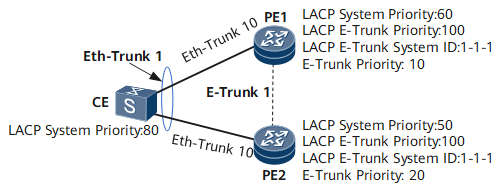
At Huawei, when Eth-Trunk is in static LACP, the member interfaces:
- By exchanging LACPDUs, they report:
- System priority (device priority),
- System ID (usually the system MAC),
- Interface priority,
- Interface number,
- Key (logical identifier of the LAG).
The side with the highest system priority (lowest numerical value) becomes the Actor. From there:
- The Actor decides which ports will be active (based on priority and policies / thresholds);
- The other side follows this decision to maintain consistency.
What needs to be “OK” for LAG to rise properly
For an Eth-Trunk with LACP to work as expected, certain points need to be aligned between the two sides:
- Same idea as LAG/Key (the doors that will form the same Eth-Trunk on each side);
- Same speed and duplex on the physical ports;
- Same type of LACP mode (static LACP on both sides);
- Coherent limits of:
- minimum number of active links (lower threshold),
- maximum number of active links (upper threshold), if used;
- Minimum compatibility in LACP timers (fast/slow) and active/passive mode (the two sides in passive do not negotiate).
What LACP does is use system priority + system ID + interface priority + interface number to:
- Decide who the actor is;
- Choose which ports are active and which are backed up.
Entering MC-LAG
So far we’ve been talking about “normal” LAG, i.e. between two devices only.
MC-LAG (Multi-Chassis LAG) comes in when you want it:
- A single LAG from the customer’s point of view (CE),
- But actually terminating in two different devices (for example, two PEs/edge routers).
The idea is simple:
- On the EC side, you can see a single Eth-Trunk with several doors;
- Physically, these ports go to two different PEs;
- On the operator’s side, these two PEs “combine” to look like a single device in terms of LACP.
MC-LAG’s main objective:
- If an entire PE dies (equipment failure, reload, etc.),
- The other PE takes over and the CE continues with the same LAG, without changing IP, MAC, gateway etc.
It’s basically taking the idea of redundancy from the port/link level to the device level.
Active/active vs active/backup
In many vendors you can find MC-LAG in two flavors:
- Active/active: both devices forward traffic at the same time;
- Active/backup: only one device is the “owner” of the LAG at any given time; the other is backed up.
At Huawei, for this specific scenario with E-Trunk/mLACP, the behavior is active/backup:
- One side is the master (active),
- The other side is backup (the links are logical down from the EC’s point of view),
- On failure, there is a switchover from the master role to the other device.
MC-LAG at Huawei: E-Trunk vs mLACP
In Huawei, there are two main ways of implementing MC-LAG:
- E-Trunk (Enhanced Trunk)
- mLACP (Multi-chassis LACP)
Both have the same goal:
“Trick” the CE into thinking it’s talking to just one device, even though there are two PEs behind it.
The difference lies in the control mechanism between the PEs:
- E-Trunk
- It uses its own channel (UDP) between the PEs, with Hello and timeout;
- Exchanges status information of the Eth-Trunks participating in that E-Trunk;
- Defines who is master and who is backup based on E-Trunk priority (lowest value = highest priority);
- Controls whether the local Eth-Trunk is up or down according to the role (master/backup) and status of the peer.
- mLACP
- It uses ICCP running over LDP between the PEs (RG – Redundancy Group);
- Synchronizes LACP configuration and status via ICCP;
- Define master/backup using mLACP system priority, system ID and port priority;
- It integrates in a more “SP standard” way with other ICCP functions (VRRP, redundant VPNs, etc.).
In this article, we’ll focus on E-Trunk, which is the “classic” form of MC-LAG in many PE-CE scenarios.
How E-Trunk works
Don’t confuse E-Trunk (the sync technology between chassis) with Eth-Trunk (the link-aggregation itself).
Consider the following scenario:
- CE dual-homed in two PEs (PE1 and PE2);
- In the EC, you create a single Eth-Trunk, with the doors going to both PEs;
- In the EPs:
- You create the same Eth-Trunk ID on PE1 and PE2;
- Place the corresponding physical interfaces on each Eth-Trunk;
- Add this Eth-Trunk to an E-Trunk with the same E-Trunk ID on both sides.
The PEs then:
- They create an E-Trunk (UDP) channel between themselves (using loopback IPs, usually);
- They exchange E-Trunk messages with:
- E-Trunk ID,
- E-Trunk priority,
- Information on Eth-Trunks members and their status;
- They define who is master and who is backup:
- Lowest E-Trunk priority wins,
- If it draws, the smaller E-Trunk system ID wins.
With that:
- On the master:
- The local Eth-Trunk participating in E-Trunk is up and running.
- No backup:
- The equivalent Eth-Trunk is in a backup state (logical down for the EC or without forwarding traffic, depending on the mode);
- The EC sees only one LAG, but in practice it is hanging from two PEs, with one of them active.
When a fault occurs:
- If the Eth-Trunk master or the PE master itself fails:
- The backup stops receiving Hello or receives a failure notification;
- The backup changes your Eth-Trunk to master and increases the LAG;
- Traffic from the EC is diverted to the other PE.
Optionally, you can:
- Integrate with BFD between PEs for faster detection;
- Use a switchback delay to avoid master/backup ping-pong.
CE connectivity ↔ PEs with E-Trunk
Some important design points:
- From the EC’s point of view, the E-Trunk is invisible:
- It only sees a normal Eth-Trunk LACP.
- In PEs, if the Eth-Trunk is L3:
- The Eth-Trunks of the two PEs usually use the same IP and MAC;
- Only the master announces a direct route; the backup does not (to avoid strange ECMP);
- Much more common is to use Eth-Trunk L2:
- The PEs participate in a common VLAN/L2 domain;
- The gateway is on another device (for example, a core/agg).
Use cases
In the topology below, we’ll cover two use cases for MC-LAG (there are many others).
- protecting a VPLS delivery to an end customer (dual approach with redundant POPs)
- protecting a /30 for the end customer (dual approach with redundant POPs)
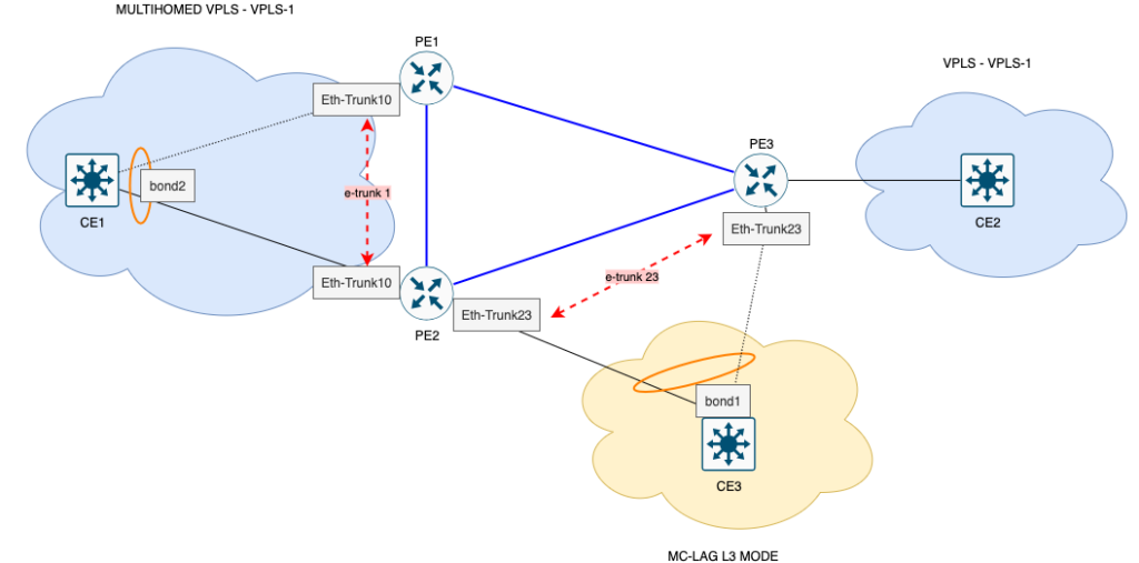
1) MC-LAG protecting VPLS (layer 2)
At the top of the drawing, CE1 is multihomed to PE1 and PE2 using MC-LAG, all in the same VPLS-1 instance.
On the network side, PE1/PE2 close the VPLS with PE3, which delivers the same service to CE2.
- From CE1’s point of view, there is only one LAG for the VPLS.
- In practice, traffic can leave via two different POPs (PE1 and PE2).
- If a POP or one of the PEs has a problem, the other continues to deliver the same VPLS to the client, without changing the VLAN, MAC or service.
This is end-to-end L2 protection for the VPLS, with equipment and POP redundancy.
2) MC-LAG protecting /30 L3 (layer 3)
At the bottom of the drawing, CE3 receives a /30 L3 via MC-LAG, dual-homed in PE2 and PE3.
- The CE3 sees a single LAG L3, with the same /30, hanging from two POPs.
- Only the PE in master state announces the direct route to this /30; the other is backed up.
- In the event of a link failure, PE or POP, there is a master/backup switchover and /30 is still accessible from the other side.
Setting up the environment
Now that you know all the concepts behind MC-LAG, let’s go to the lab. We’re going to use the PNETLAB virtual environment, with the Huawei NE40 V22 image.
The physical ports and connections between devices are described in the topology below.
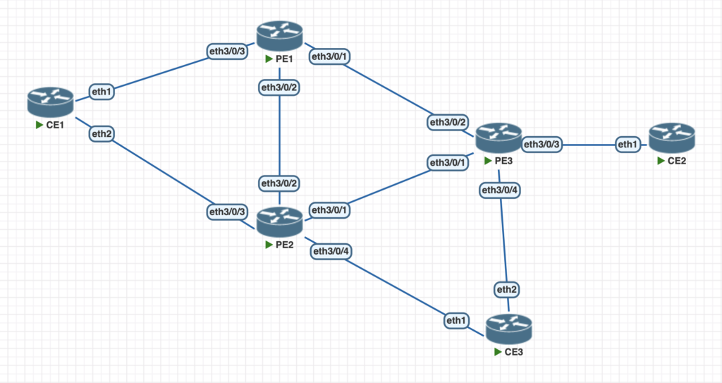
The configuration of the CEs is simple: a mikrotik (ROS 7.6) using bonding interfaces, with LACP fast (in 1s). CE3 is simply a physical interface with a VLAN.
CE1
# configura o hostname
/system identity set name=CE1

# cria o LAG bond2 usando LACP entre as portas ether1 e ether2
/interface bonding add lacp-rate=1sec mode=802.3ad name=bond2 slaves=ether1,ether2

# adiciona a vlan 10 , utilizada no VPLS, ligada no LAG bond2
/interface vlan add interface=bond2 mtu=1488 name=vlan10 vlan-id=10

# configura o IP na vlan10
/ip address add address=10.10.10.1/24 interface=vlan10 network=10.10.10.0
CE2
# configura o hostname
/system identity set name=CE2

# adiciona a vlan 10 , utilizada no VPLS, ligada diretamente na ether1
/interface vlan add interface=ether1 name=vlan10 vlan-id=10

# configura o IP na vlan10
/ip address add address=10.10.10.2/24 interface=vlan10 network=10.10.10.0
CE3
# configura o hostname
/system identity set name=CE3

# cria o LAG bond1 usando LACP entre as portas ether1 e ether2
/interface bonding add lacp-rate=1sec mode=802.3ad name=bond1 slaves=ether1,ether2

# adiciona o IP /30 direto na interface bond1
/ip address add address=10.23.23.2/30 interface=bond1 network=10.23.23.0

# configura o gateway default
/ip route add gateway=10.23.23.1
The configuration of the PEs includes the point-to-point interfaces, active with OSPF, MPLS. On the access interfaces, the LAG and e-trunk synchronization configurations. And in the service layer, we have set up the VPLS (VSI) and also the L3 gateway (with the mac-address and the same IP).
PE1 – Core Layer
# configura o hostname
sysname PE1

# habilita o bfd
bfd

# configura e ativa o mpls e o l2vpn
mpls lsr-id 1.1.1.1
mpls
mpls l2vpn
mpls ldp

# configura o ospf e ativa a area 0
ospf 1 router-id 1.1.1.1
 opaque-capability enable
 area 0.0.0.0

# configura a loopback
interface LoopBack1
 ip address 1.1.1.1 255.255.255.255
 ospf enable 1 area 0.0.0.0

# configura as interfaces fisicas com o /30 e ativando ospf/mpls
interface Ethernet3/0/1
 description to_PE3
 undo shutdown
 ip address 10.1.3.1 255.255.255.0
 ospf cost 1000
 ospf network-type p2p
 ospf enable 1 area 0.0.0.0
 mpls
 mpls ldp
 undo dcn
 undo dcn mode vlan
#
interface Ethernet3/0/2
 description to_PE2
 undo shutdown
 ip address 10.1.2.1 255.255.255.0
 ospf network-type p2p
 ospf enable 1 area 0.0.0.0
 mpls
 mpls ldp
 undo dcn mode vlan
MLAG and E-trunk service
This is where MLAG really comes into its own. We first create an ordinary Eth-Trunk, and then associate it with an e-trunk configuration, which makes the MLAG magic happen.
# cria a Eth-Trunk10
interface Eth-Trunk10
 mode lacp-static
 lacp timeout fast

# associa a interface ao eth-trunk
interface Ethernet3/0/3
 description to_CE1
 undo shutdown
 eth-trunk 10
With the LAG created, we now need to create the e-trunk configuration. To configure it, we need to:
- of the remote peer IP (the session is closed between loopbacks)
- set the priority between routers (lower is better)
- setting the timers (in multiples of 100ms)
- configure authentication for security
- add a description to e-trunk
- configure the system-id and priority of the e-trunk (these settings “trick” the remote peer into thinking it’s the same device)
In our lab, we’ll close the loopback between PE1 and PE2 – these are part of the MLAG from CE1’s perspective. The master priority will be PE2, with priority 5. The timers configured are 9 for hello and 30 for hold-timer.
# configura os parametros de system-id e prioridade do e-trunk
lacp e-trunk system-id 00e0-beba-cafe
lacp e-trunk priority 1

# cria a sessao BFD entre os peers PE1 e PE2
bfd hello bind peer-ip 2.2.2.2 source-ip 1.1.1.1
 discriminator local 1
 discriminator remote 2

# cria o etrunk-1
e-trunk 1
 # a descricao
 description PE1_to_PE2

 # configura a prioridade
 priority 10

 # diz quais os peers da comunicacao
 peer-address 2.2.2.2 source-address 1.1.1.1

 # configura timers
 timer hello 9
 timer hold-on-failure multiplier 30

 # autenticacao/senha
 authentication-mode enhanced-hmac-sha256
 security-key cipher %^%#dX@~~;axSXr!.(&d<4PYE)n7:!hcBBD-`2>JeFa!%^%#

 # associa a sessao BFD com o e-trunk
 e-trunk track bfd-session session-name hello
Finally, it’s time to associate the LAG interface with e-trunk, thus creating an MLAG from CE1’s perspective.
# associa o e-trunk ao Eth-Trunk, criando assim o MLAG
interface Eth-Trunk10
 e-trunk 1
VPLS services
# cria o VPLS chamado VPLS-1
vsi VPLS-1 static
 pwsignal ldp
  vsi-id 1
  mac-withdraw enable
  interface-status-change mac-withdraw enable
  peer 3.3.3.3
 ignore-ac-state

# cria a interface da vlan10 e associa o VPLS
interface Eth-Trunk10.10
 vlan-type dot1q 10
 l2 binding vsi VPLS-1
PE2 – Core Layer
The CORE and VPLS configurations of PE2 are similar to those of PE1
MLAG and E-trunk service
# configura os parametros de system-id e prioridade do e-trunk
lacp e-trunk system-id 00e0-beba-cafe
lacp e-trunk priority 1

# cria o lagg e associa a interface fisica de acesso
interface Eth-Trunk10
 mode lacp-static
 lacp timeout fast

interface Ethernet3/0/3
 description to_CE1
 undo shutdown
 eth-trunk 10

# cria a sessao BFD
bfd hello bind peer-ip 1.1.1.1 source-ip 2.2.2.2
 discriminator local 2
 discriminator remote 1

# cria o etrunk1 com o PE1
e-trunk 1
 priority 5
 peer-address 1.1.1.1 source-address 2.2.2.2
 timer hello 11
 timer hold-on-failure multiplier 33
 security-key cipher %^%#tv.DQ.!Y,C7ga=SnUvtMsT84Xld,eBTM\\6fSq#2%^%#
 e-trunk track bfd-session session-name hello
 authentication-mode enhanced-hmac-sha256
 description PE1_to_PE2

# associa o e-trunk ao LAG
interface Eth-Trunk10
 e-trunk 1
Redundant Gateway Services
For the redundant gateway service for CE3, we will:
- establish a LAG between PE2xCE3 and a lag between PE3xCE3
- activate e-trunk between PE2 and PE3 in the lag created
- configure e-trunk’s system-id and priority parameters
- configure the same IP address and mac-address on the Eth-trunk interface on both routers
- add the interface to OSPF
# configura os parametros de system-id e prioridade do e-trunk
lacp e-trunk system-id 00e0-beba-cafe
lacp e-trunk priority 1

# cria o LAG Eth-Trunk23
interface Eth-Trunk23
 mode lacp-static
 lacp timeout fast

# adiciona a interface ao LAG
interface Ethernet3/0/4
 description to_CE3
 eth-trunk 23

# cria a sessao BFD entre o PE2 e PE3
bfd peer_r2_r3 bind peer-ip 3.3.3.3 source-ip 2.2.2.2
 discriminator local 23
 discriminator remote 32

# cria o e-trunk23 entre os roteadores
e-trunk 23
 priority 5
 peer-address 3.3.3.3 source-address 2.2.2.2
 timer hold-on-failure multiplier 30
 security-key cipher %^%#tv.DQ.!Y,C7ga=SnUvtMsT84Xld,eBTM\\6fSq#2%^%#
 e-trunk track bfd-session session-name peer_r2_r3
 authentication-mode enhanced-hmac-sha256
 description PE2_to_PE3

# associa o e-trunk ao Eth-Trunk, formando assim o MLAG
interface Eth-Trunk23
 e-trunk 23

# finalmente, configura o endereçamento IP, mac e adiciona no OSPF a interface
interface Eth-Trunk23
 ip address 10.23.23.1 255.255.255.252
 ospf enable 1 area 0.0.0.0
 mac-address 00e0-beba-cafe
PE3 – Core Layer
PE3’s CORE configurations are similar to those of PE1.
VPLS services
Unlike PE1 and PE2, which have an MLAG with the CE, in this case PE3xCE2 communication takes place directly on the physical interface with vlan 10. The VPLS settings remain the same, the difference is in the peers, which close the VPLS with PE1 and PE2 at the same time.
# cria o VPLS e adiciona os PE1 e PE2
vsi VPLS-1 static
 pwsignal ldp
  vsi-id 1
  mac-withdraw enable
  interface-status-change mac-withdraw enable
  peer 1.1.1.1
  peer 2.2.2.2
 ignore-ac-state

# habilita a interface com o CE2
interface Ethernet3/0/3
 description to_CE2
 undo shutdown

# cria a interface vlan 10 e associa ao VPLS
interface Ethernet3/0/3.10
 vlan-type dot1q 10
 l2 binding vsi VPLS-1
Redundant Gateway Services
# configura os parametros de system-id e prioridade do e-trunk
lacp e-trunk system-id 00e0-beba-cafe
lacp e-trunk priority 1

# cria o LAG Eth-Trunk23
interface Eth-Trunk23
 mode lacp-static
 lacp timeout fast

# adiciona a interface ao LAG
interface Ethernet3/0/4
 description to_CE3
 eth-trunk 23

# cria a sessao BFD entre o PE2 e PE3
bfd peer_r3_r2 bind peer-ip 2.2.2.2 source-ip 3.3.3.3
 discriminator local 32
 discriminator remote 23

# cria o e-trunk23 entre os roteadores
e-trunk 23
 priority 5
 peer-address 2.2.2.2 source-address 3.3.3.3
 timer hold-on-failure multiplier 30
 security-key cipher %^%#tv.DQ.!Y,C7ga=SnUvtMsT84Xld,eBTM\\6fSq#2%^%#
 e-trunk track bfd-session session-name peer_r2_r3
 authentication-mode enhanced-hmac-sha256
 description PE3_to_PE2

# associa o e-trunk ao Eth-Trunk, formando assim o MLAG
interface Eth-Trunk23
 e-trunk 23

# finalmente, configura o endereçamento IP, mac e adiciona no OSPF a interface
interface Eth-Trunk23
 ip address 10.23.23.1 255.255.255.252
 ospf enable 1 area 0.0.0.0
 mac-address 00e0-beba-cafe
Validating configurations and redundancy
MC-LAG between devices
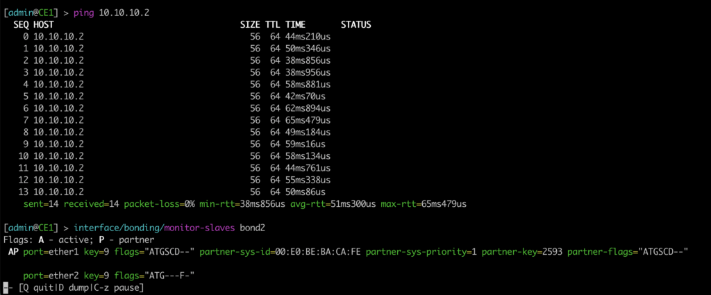
In CE1’s view, it has two active ports in LAG bond2, the ether2 port – which talks to PE2 – being the main one. The other is ready for use, but with the flags of not forwarding traffic.

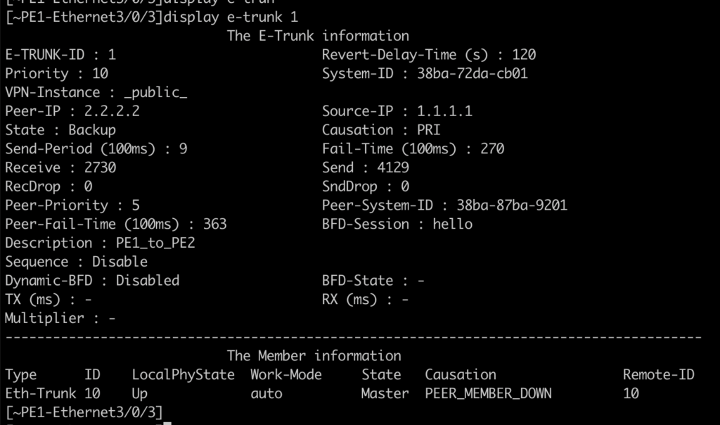
On the PE1 side, it finds Eth-Trunk1 with the UP state, but the DOWN protocol, with the cause E-TRUNK DOWN. This is because MLAG is active/backup, so the router with the worst priority is in the backup state.
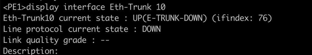
We can see that on PE1, e-trunk is as a backup:

On PE2, we see the Eth-Trunk 10 interface as UP. And the Eth-trunk10.10 interface as UP.
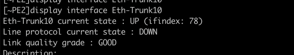
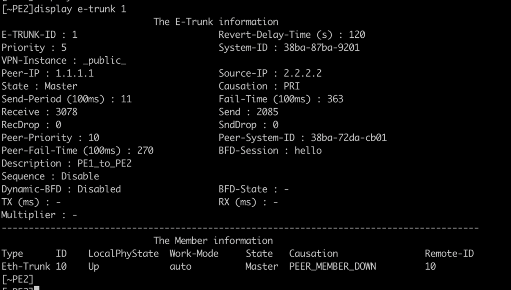
We can see that e-trunk is up, and as a master:
VPLS Service
To test the VPLS service, let’s go:
- ping between ECs
- validate which interface the traffic is passing through
- take down the main interface on PE2
- verify that the traffic immediately converged on the other link
Traffic through ether2, with ping between the ECs:

Dropping the access interface on PE2 (simulating a break), and at the same time checking the reconvergence:
Virtually no losses! LACP/LAG simply switched to the link from ether1 to PE1. In this case, the e-trunk was UP on PE1:
Redundant gateway service
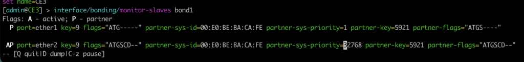
The redundant gateway service can be checked directly in CE3.
The active port on CE3 is ether2, connected to PE3:
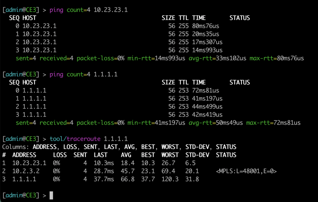
We have pinged the gateway and also the PE1 loopback. We also traceroute through PE3xPE2xPE1 (preferred path due to the cost handled in OSPF).
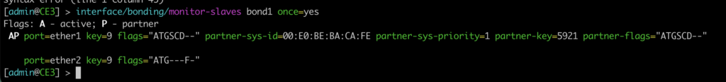
Here we’ll bring down the physical interface on PE3, at the same time as a ping is run from CE2 to PE1’s loopback. And at the end we see the traceroute change.

Change LACP to port ether1.
Status of e-trunk in PE3 and PE2:
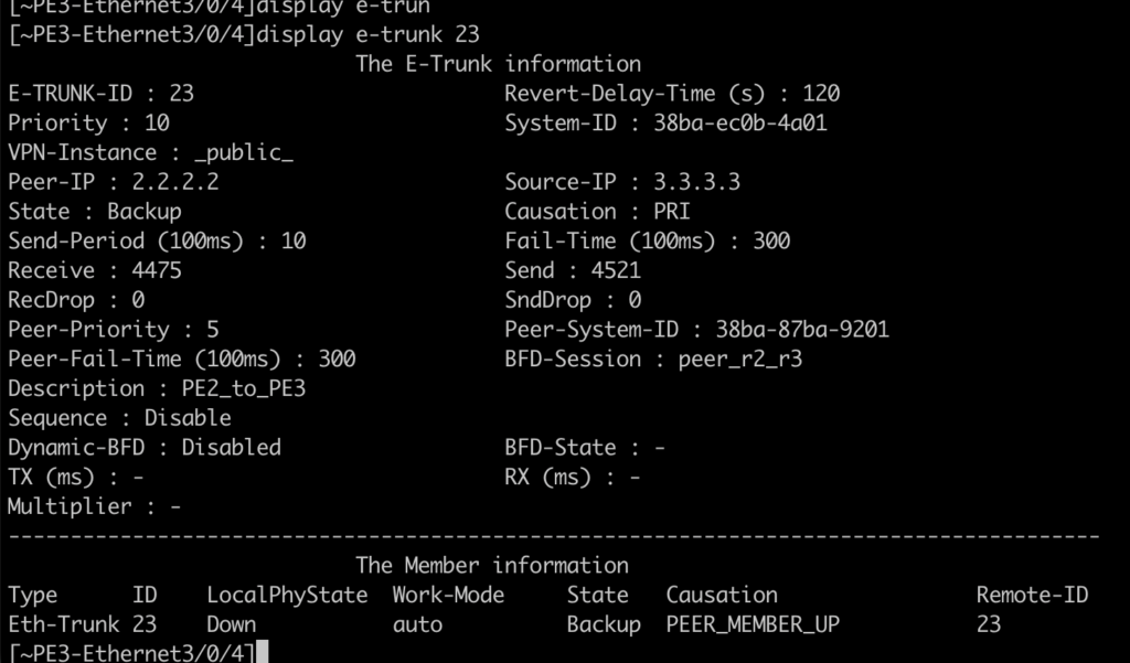
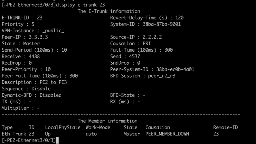
And why wasn’t it “so” transparent this time? Why didn’t the VPLS service behave the same way?
The answer lies in a new element: internal routing for the gateway block. For this scenario, the router that is active is the one that generates the route in OSPF:
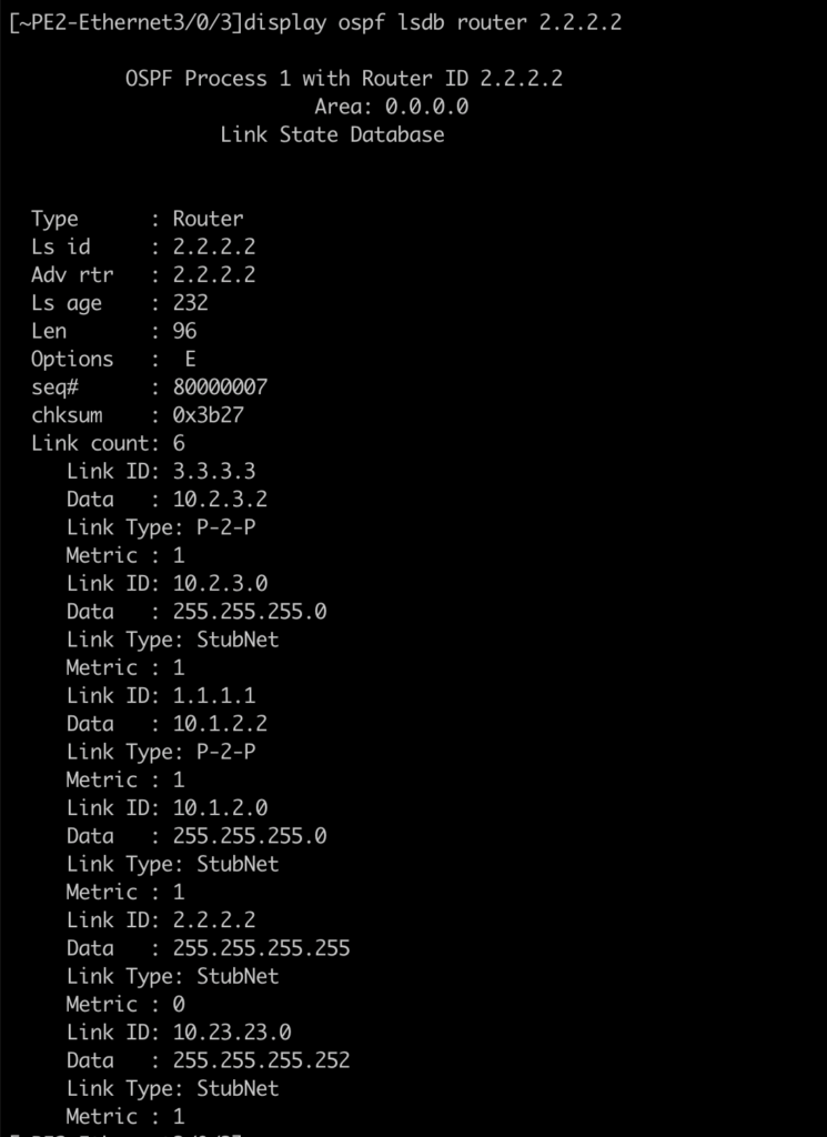
PE3, which has had its interface shut down, does not generate the route:

So in answer, the delay is due to the fact that as well as switching LACP via e-trunk, the entire OSPF network had to recalculate the new route to the new router, adding a few seconds to the game (PE3 flooded the network with the LSA, bringing down the 10.23.23.0/24 network, the entire network processed and recalculated the SPF, and then PE2, when reconverting the e-trunk/lacp, generated the 10.23.23.0/24 network again).
Conclusions
MC-LAG is very useful for ensuring the high availability not only of links, but also of devices and even POPs. It has proved viable for various types of service, both L2 and L3. Huawei’s e-trunk protocol is very light and versatile, and uses intelligent mechanisms such as BFD to make everything faster. Its big disadvantage is that we don’t have an Active/Active MLAG, meaning that one of the circuits (or set of circuits) will always be idle.
Did you know about MC-LAG? I hope you enjoyed the article, and if you need help, Made4it can help you. We specialize in networks with high availability and security.
I WANT HIGH AVAILABILITY