
Welcome, dear readers and network enthusiasts! If you’ve made it this far, it’s because you’ve already survived the theory of SRv6 (Segment Routing IPv6) in our first two articles. If you haven’t already, I recommend taking a look at them so you don’t feel as lost as a packet without a router.
After all, nobody wants to be the lost packet on the network, right?
In the first chapters of our SRv6 saga, we delved into the concepts and theory behind the protocol. If you don’t remember, go there and review the articles:
https://made4it.com.br/srv6-um-sucessor-do-mpls/
https://made4it.com.br/srv6-um-sucessor-do-mpls-parte-2/
Now it’s time to get your hands dirty and see how it all works in practice. It’s like building a LEGO Millennium Falcon after reading the instruction manual. Let’s put this structure together step by step!
Get your terminals ready, buckle up and let’s take off in this basic SRv6 configuration lab.
If you’re ready to turn theory into practice and master yet another networking Jedi skill, join me!
The laboratory
The aim of the lab is to create a simple topology with SRv6, using ISIS as the IGP and BGP to signal L2VPN.
We will use the “END-DX2” SID to transport L2VPN within our SRv6 environment.
For our lab we are using 6 Huawei NE40E-M2K routers (V800R022C10SPC500), acting as nodes in the IPv6 Segment-Routing network.
We also have 2 Mikrotik routers (RouterOS 7.6), simulating the network CEs.
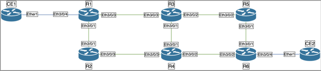
Physical topology:
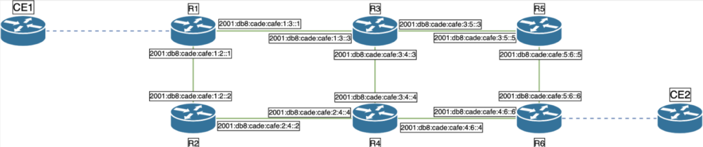
Topology with IPv6 addressing:
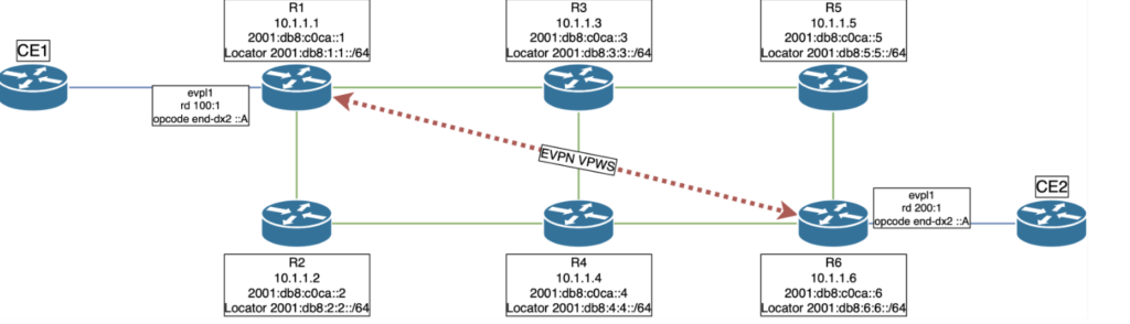
Topology with services:
We can see from the topologies that someone certainly likes coffee a lot.
Without further ado, let’s get down to business.
Configuration roadmap
- Task 1: Configure IS-IS on all routers.
- Task 2: Configure Loopbacks with IS-IS support.
- Task 3: Configure link networks with IS-IS support.
- Task 4: Enable SRv6 globally
- Task 5: Configure BGP with L2VPN support on PEs
- Task 6: Create VPN VPWS and SID End.DX2 on R1 and R6.
- Task 7: Link EVPL to interfaces with ECs
- Task 8: Checks
Easy Peasy.
Task 1: Configure IS-IS on all routers.
First, we configured IS-IS as the level 2 routing protocol on all routers, enabling IPv6.
R1:
system-view
isis 1
is-level level-2
cost-style wide
network-entity 10.0000.0000.0001.00
#
ipv6 enable topology ipv6
#
R2:
system-view
isis 1
is-level level-2
cost-style wide
network-entity 10.0000.0000.0002.00
#
ipv6 enable topology ipv6
#
Follow the configuration of the other routers according to the documentation.
Task 2: Configure Loopbacks with IS-IS support
Configure the Loopback interfaces on each router with IPv4 and IPv6 addresses and enable IS-IS.
R1:
system-view
interface LoopBack0
ipv6 enable
ip address 10.1.1.1 255.255.255.255
ipv6 address 2001:DB8:C0CA::1/128
isis ipv6 enable 1
#
R2:
system-view
interface LoopBack0
ipv6 enable
ip address 10.1.1.2 255.255.255.255
ipv6 address 2001:DB8:C0CA::2/128
isis ipv6 enable 1
#
Follow the configuration of the other routers according to the documentation.
Task 3: Configure link networks with IS-IS support
Configure the Ethernet interfaces interconnected between the routers with IPv6 addresses and enable IS-IS.
R1 – Ethernet3/0/1- Connected to router R2.
system-view
interface Ethernet3/0/1
description Connected to Eth3/0/1 - R2
undo shutdown
ipv6 enable
ipv6 address 2001:DB8:CADE:CAFE:1:2:0:1/96
isis ipv6 enable 1
#
R1 – Ethernet3/0/3 – Connected to router R3.
system-view
interface Ethernet3/0/3
description Connected to Eth3/0/3 - R3
undo shutdown
ipv6 enable
ipv6 address 2001:DB8:CADE:CAFE:1:3:0:1/96
isis ipv6 enable 1
#
Follow the configuration of the other routers according to the documentation.
Task 4: Enable SRv6 globally
Configure SRv6 on each router, defining source addresses and locators, and integrating them with IS-IS
R1:
system-view
segment-routing ipv6
encapsulation source-address 2001:DB8:C0CA::1
locator R1 ipv6-prefix 2001:DB8:1:1:: 64 static 32
#
isis 1
segment-routing ipv6 locator R1
#
#
R2:
system-view
segment-routing ipv6
encapsulation source-address 2001:DB8:C0CA::2
locator R2 ipv6-prefix 2001:DB8:2:2:: 64 static 32
#
isis 1
segment-routing ipv6 locator R2
#
#
Follow the configuration of the other routers according to the documentation.
Task 5: Configure BGP with L2VPN support on PEs
Configure BGP with EVPN and L2VPN support on the edge routers (R1 and R6), creating BGP sessions between them.
R1:
system-view
evpn source-address 10.1.1.1
bgp 65000
router-id 10.1.1.1
peer 2001:DB8:C0CA::6 as-number 65000
peer 2001:DB8:C0CA::6 connect-interface LoopBack0
#
l2vpn-family evpn
undo policy vpn-target
peer 2001:DB8:C0CA::6 enable
y
peer 2001:DB8:C0CA::6 advertise encap-type srv6
#
R6:
system-view
evpn source-address 10.1.1.6
bgp 65000
router-id 10.1.1.6
peer 2001:DB8:C0CA::1 as-number 65000
peer 2001:DB8:C0CA::1 connect-interface LoopBack0
#
l2vpn-family evpn
undo policy vpn-target
peer 2001:DB8:C0CA::1 enable
y
peer 2001:DB8:C0CA::1 advertise encap-type srv6
#
Task 6: Create EVPN/EVPL and SID End.DX2 on PEs
Configure the EVPN/EVPL instances and associate the appropriate SRv6 locators on the edge routers.
R1:
system-view
evpn vpn-instance evrf1 vpws
route-distinguisher 100:1
segment-routing ipv6 best-effort
vpn-target 1:1 export-extcommunity
vpn-target 1:1 import-extcommunity
#
evpl instance 1
evpn binding vpn-instance evrf1
local-service-id 100 remote-service-id 200
segment-routing ipv6 locator R1
#
segment-routing ipv6
locator R1
opcode ::A end-dx2 evpl-instance 1
#
R6:
system-view
evpn vpn-instance evrf1 vpws
route-distinguisher 200:1
segment-routing ipv6 best-effort
vpn-target 1:1 export-extcommunity
vpn-target 1:1 import-extcommunity
#
evpl instance 1
evpn binding vpn-instance evrf1
local-service-id 200 remote-service-id 100
segment-routing ipv6 locator R6
#
segment-routing ipv6
locator R6
opcode ::A end-dx2 evpl-instance 1
#
Task 7: Link EVPL to interfaces with ECs
Associate the EVPL instances with the interfaces connected to the client routers (CEs).
R1:
interface Ethernet3/0/4
description Connected to CE1
undo shutdown
evpl instance 1
#
R6:
system-view
interface Ethernet3/0/4
description Connected to CE2
evpl instance 1
#
Task 8: Checks
Once configured, let’s do some checks on the technologies involved:
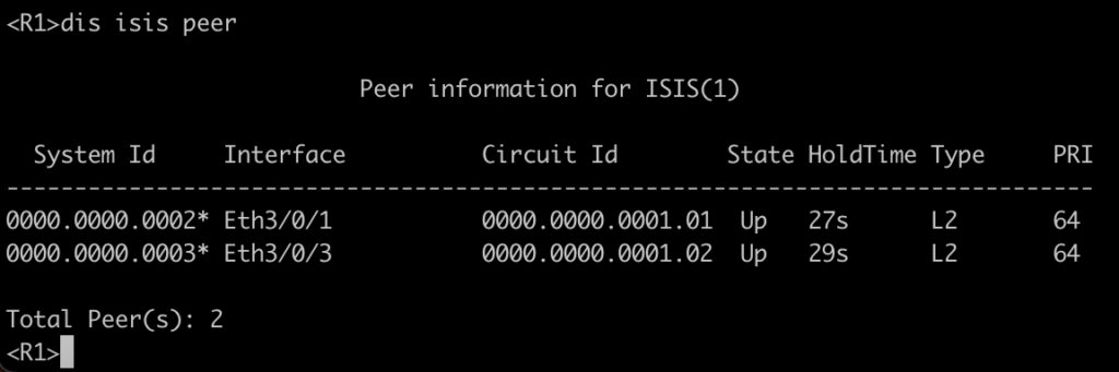
8.1: Adjacencies of the IGP.
Confirm the IS-IS adjacencies between the routers.
Once configured, let’s do some checks on the technologies involved:
8.2: IS-IS route table.
Below is the output of router R1’s routing table:
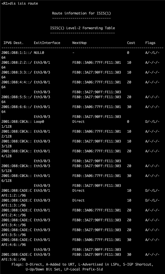
One nice thing we’ve noticed here is routes for “Locator” prefixes (/64).
In other words, the environment already knows in its routing table the prefix used for the SRv6 of each of the nodes in the topology 😊
8.3: BGP table “EVPN” of router R1, to ensure that we have the session between R1 and R6 required for VPWS.
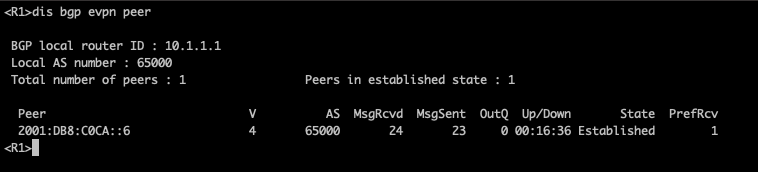
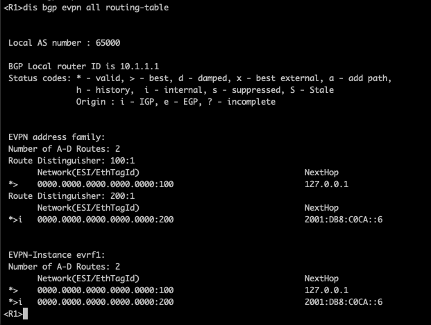
We can see that R1 has an established and functional session with router R6. R1’s routing table also shows an ESI for R6 in RD 200:1. So far, everything is ready for the environment to transition to VPWS.
8.4: EVPL on router R1 and R6. Below, the output of router R1.
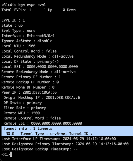
We see in R1 that the EVPL is UP, and the tunnel used to transit the packets within the network is of the “SRv6-BE” type (Segment Routing IPv6 – Best Effort).
This indicates that the VPWS is closed and functional between the head-end and tail-end and also that the transport tunnel between the PEs is using SRv6.
8.5: Local SID table for router R1:
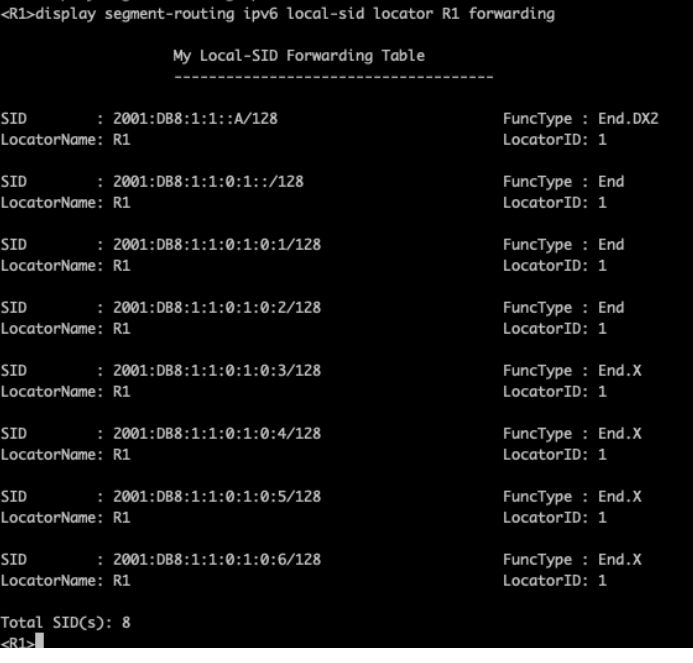
Looking at the local table of SIDs allocated to R1, we see not only the SID configured for VPWS but also some SIDs of type “END” and type “END.X”.
What really matters to us at the moment is the “End.DX2” SID, which says that anything sent to the IPv6 address 2001:db8:1:1::a/128 will be delivered to our VPWS.
If you’re curious what the other SIDs are all about, stay tuned for future blog posts 😀
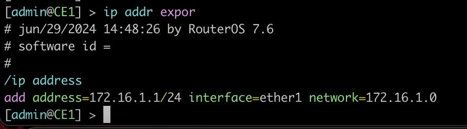
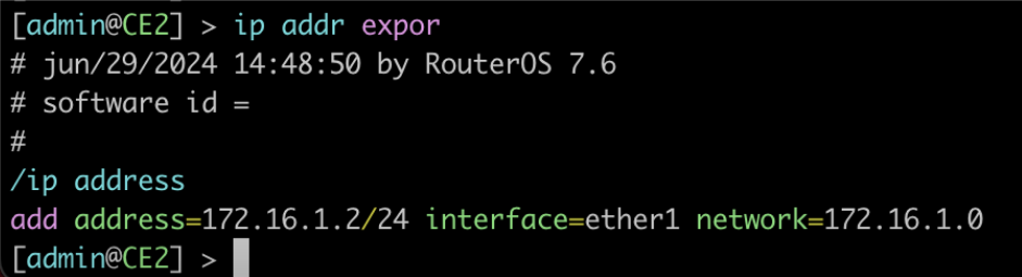
8.6: Configuration and communication of ECs.
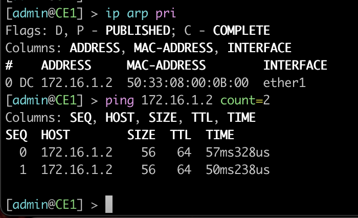
Interfaces of ECs 1 and 2, with an IPv4 address for communication.
ARP table from CE1 and a ping to CE2, confirming connectivity between the CEs.
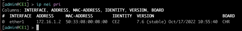
Neighbors LLDP in CE1, showing the path being “Transparent” from the ECs point of view.
8.7: While CE1 is exchanging pings with CE2, a packet capture on router R1’s interface to the rest of the SRv6 network has the following output:
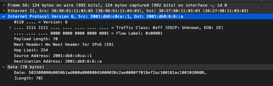
EVPN packets are encapsulated and, when they are forwarded to the SRv6 network, the “destination address” becomes 2001:db8:6:6::A, this being the “SID” END.DX2″.
The most interesting thing about SRv6 is that the package is “IPv6”. If our environment contained only SRv6-supporting PEs, the rest of the network would know how to forward traffic without any problems 😊
Summary
In this lab, we explore the configuration of an L2VPN tunnel using SRv6, showing the basic configurations of each device.
SRv6, with its advanced capabilities, is proving to be a promising technology for the networks of the future. To explore the application of SRv6 in your network, contact Made4IT, a specialist in the field. We can help you migrate from MPLS to SRv6, working on the coexistence of these protocols.
Complete configurations
Download this complete lab, with topologies, configurations and roadmap here:
Authors:
Gabriel Henrique, Network and Project Analyst at Made4it.
Rafael Ganascim, Co-Founder of Made4it.